Date: October 11, 2022
FIRE PUMP QUICK START GUIDE
Are you a member of an apparatus committee that is working to create a spec for your new apparatus? There are many decisions, terminologies and options that will be discussed and suggested as you move toward completing the truck spec including what type of fire pump to select, pump location, single or multi-stage, full-bodied or end suction.
This article will focus on the more common municipal applications basics, however later in this article, a link is provided if you are interested in ARFF, Motor Pumps, CAFS or Foam systems
The first step in working on your pump application is to identify where you would like the pump mounted in the fire apparatus?
Choosing a Location:
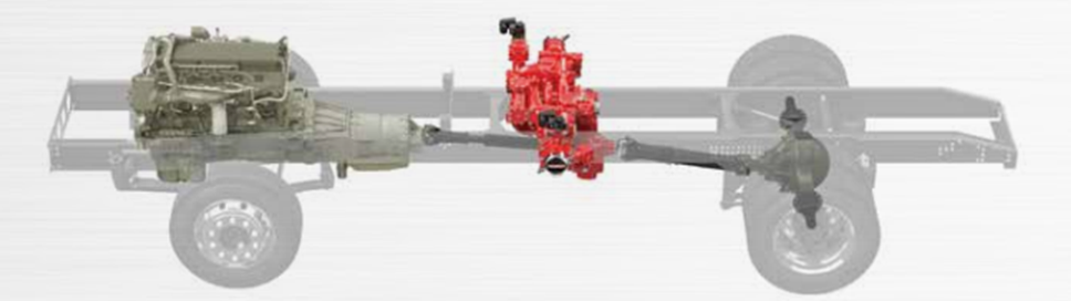
Midship Mounted: The term “Midship” is a common term in the fire service which means a fire pump is mounted in the middle of the fire apparatus, behind the cab. The term midship, does not designate however how the fire pump is being driven nor does it designate body style of the pump (full body vs. end suction. More on the pump drive and pump body style later).
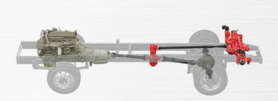
Rear Mounted: Rear mounted is exactly as it sounds. The pump whether it is a full-body or end-suction is mounted in the rear of the apparatus.
Choosing a Single- or Multi-Stage Pump:
The decision to choose a single- or multi-stage pump seems to be a lack of understanding of the options available and the advantages of each. This article will discuss differences between single and two-stage pumps. Three and four stage pumps are also readily available, but generally are only specified when very high discharge pressures are required.
Three Main Criteria: Single-stage or two-stage pump
- Performance
- Pump life
- Cost
Performance
NFPA 1900 Standard for Automotive Fire Apparatus makes no distinction between a single-stage and two-stage pump. Both pumps must pass the same performance tests listed in the standard. So, in essence, either pump will do the same thing. The difference is that they are not designed to do the same thing. One pump will operate more efficiently than the other at certain operating conditions. The reasons for this are beyond the scope of this article, but the actual differences are worth exploring.
Single-Stage Pumps
Single-stage pumps are designed to flow large volumes of water. If you have an apparatus that frequently flows at or near the rated capacity of the pump, then a single-stage pump will probably be the best choice. It will flow rated capacity more efficiently (with less engine speed) than a two-stage pump (even though both pumps may have the same rated capacity (i.e., 1500 gpm). Single-stage pumps work best when pumping at or near their rated capacity.
But most fire departments pumpers don’t operate at or near their rated capacity all the time. In fact, they most commonly are used to pump only a fraction of their rated capacity. Look at the apparatus in your fleet. When was the last time a pump flowed rated capacity at a fire call? For many departments (including the larger fleets), most fires are extinguished with one handline flowing about 100 gpm.
Two-Stage Pumps
Two-stage series/parallel pumps are really ‘two pumps in one”. When operated in the VOLUME (parallel) position, they mimic the design of the single-stage pump. In the PRESSURE (series) position, they will flow up to 70% of their rated capacity more efficiently (with less engine speed) than a single stage pump.
The table below shows the pump speeds and horsepower required to obtain various common fireground flows using a 1500 gpm pump. The actual numbers may vary between pump manufacturers, but the comparisons will be similar.
|
|
Single-stage |
Two-stage – PRESSURE (series) Position |
||
|
Performance |
RPM |
HP |
RPM |
HP |
|
100 gpm @ 150 psi |
3215 |
74 |
2300 |
32 |
|
200 gpm @ 150 psi |
3235 |
79 |
2315 |
38 |
|
500 gpm @ 150 psi |
3220 |
91 |
2515 |
67 |
Pump Life
So, the two-stage pump is more efficient at most flow rates – what does that really mean to me? The short answer is – it means a lot. If you are using a single-stage pump to flow less than rated capacity, you will need to spin it faster than a two-stage pump. This results in additional fuel consumption for the engine. A typical diesel engine consumes about 20 gallons of fuel per hour when run at governed speed. This may not sound like much, but over the life of the apparatus – and with today’s fuel prices – the dollars can add up quickly.
Also, running the engine faster than necessary results in additional wear-and-tear on the engine, chassis transmission and driveline components. This is not a huge consideration for most departments since today’s engines, transmissions and drivelines that are used in fire apparatus are basically the same design that are used in over-the-road trucks which run hundreds of thousands of miles before needing to be overhauled. But there is still no getting around the fact that using a two-stage pump will decrease the amount of wear-and-tear on these components.
By far the biggest advantage to using two-stage pumps is they will last longer. As stated above, if you are using a single-stage pump to flow less than rated capacity, you will need to spin it faster than a two-stage pump. This will cause the pump to wear out faster. Again, this may not be a huge consideration for some departments that do not respond to many calls, but for busy departments this could result in an unexpected premature budget-busting pump overhaul job.
More importantly, the faster you run a diesel engine, the more horsepower it will develop. The pump, however, will only require a fraction of the horsepower being sent to it from the engine. The excess horsepower will be converted into heat energy. This will cause the water in the fire pump to heat up. If the water gets too hot, a catastrophic pump failure is imminent.
Finally, as noted above, single-stage pumps are designed to flow large volumes of water. They are not designed to produce high pressures. In fact, to develop 125 gpm at 200 psi (a typical 300’ 1-1/2 attack line), a single stage pump will need to spin faster than it would to pump 1500 gpm at 150 psi. At this speed, the impeller wants to flow in excess of 1500 gpm. But the nozzle at the end of the hose is limiting the flow through the impeller to 125 gpm. This results in an extreme amount of turbulence inside the pump as the water leaving the impeller has no place to go. This phenomenon results in what is known as ‘recirculation cavitation’ which can quickly destroy a centrifugal pump. Using a two-stage pump to develop the same 125 gpm at 200 psi requires about 25% less speed, which greatly reduces the amount of recirculation cavitation inside the pump.
Cost
Two-stage pumps are comparable in cost to single-stage pumps.
Conclusions
Two−stage series/parallel pumps are preferred over single−stage pumps for the following reasons:
- Pumper performance is better with a two−stage pump over almost the entire operational range, and particularly at capacities less than 70 percent of rated capacity and pressures greater than 150 psi.
- Pump life is greater for two−stage units, particularly if pumpers are used often for low capacity/high pressure applications.
- The additional operator training required for pumpers having two−stage series/parallel pumps is minimal.
- The cost of a two-stage pump is comparable to the cost of a single-stage pump.
Choosing Between a Full Body (Dual Eye Impeller) or End Suction (Single Eye Impeller)
Before you select this option, let’s look at the differences and similarities between an end-suction pump and a full-bodied pump.
Pump Designations
CS Series is a full-bodied, single stage pump with ratings up to 1250 GPM. Adding the U designation to the CS, the CSU Series is rated up to 2250 GPM. Both CS and CSU Series have dual-eye impellers.
CXV Series is a single-stage, end suction pump with ratings available at 750, 1000, 1250 GPM. CXS Series is rated up to 1500 GPM. Both CXV and CXS Series have single-eye impellers.
S100 is a single-stage, end suction pump with ratings up to 2000 GPM. S100 Series have single-eye impellers.
NOTE: The eye or center of the impeller is where the water enters the impeller.
Waterous pumps are available in different ratings. For this instance, we will choose the 1500 GPM version of each pump: CSU Series full bodied dual-eye impeller, CXS and S100 Series end suction single eye impeller.
SIMILARITIES ON ALL WATEROUS PUMPS
- Made in the USA
- 7-year warranty
- Can be midship or rear mounted
- Can be split shaft (C22 pump transmission) or PTO driven (*GPM ratings for PTO driven applications vary, please consult before determining a PTO rating)
- Similar pump operation (controls, drafting, priming, engage & disengage)
- All are rated at 1500 GPM @ 150 psi
- All have bronze impellers
- All are capable of an integrated Compressed Air Foam System
- Available to all OEM’s
DIFFERENCES
CSU Water Flow (Full body, dual-eye impeller)
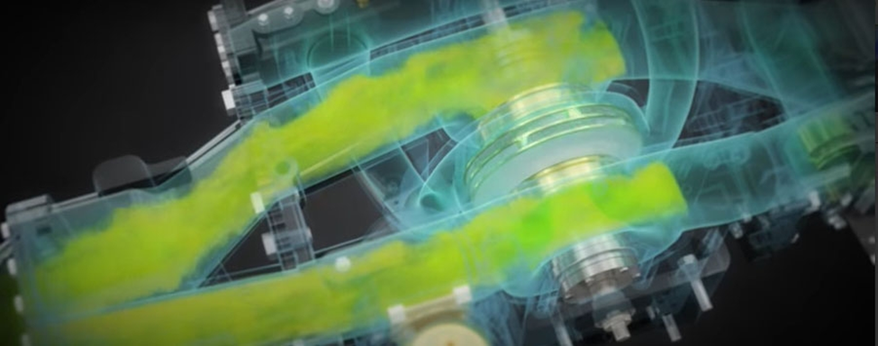
With the CSU, water enters the pump through intake manifolding and the inbound water stream is split. Half of the water flows to the impeller eye at the front of the impeller, the other half flows to the impeller eye at the rear. The water is pressurized by the rotation of the impeller.
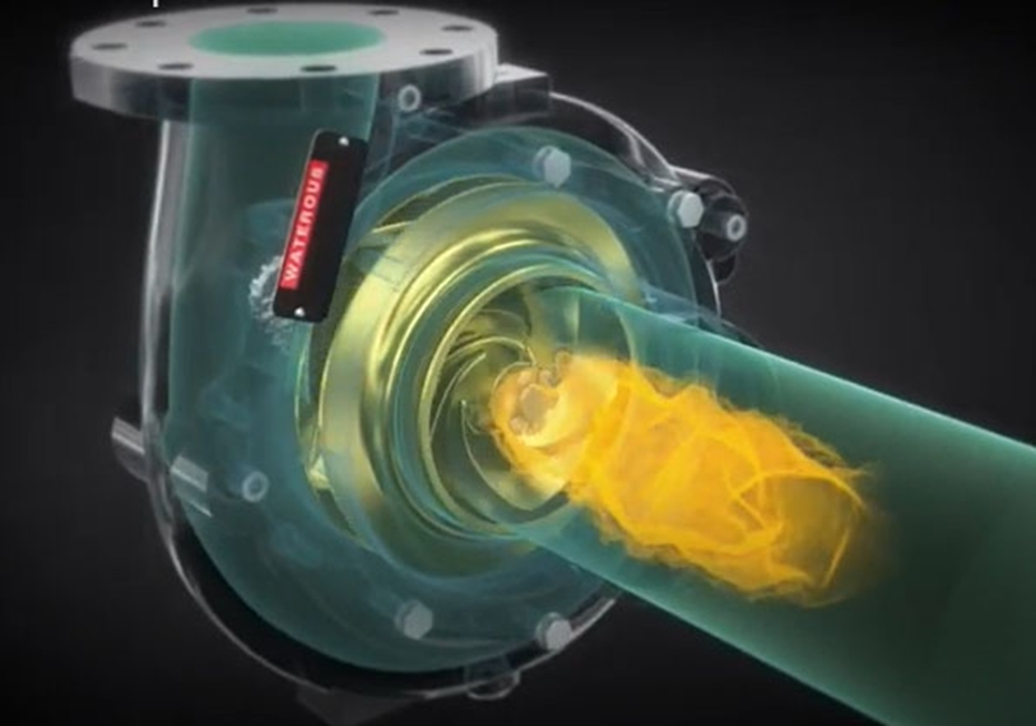
With the end suction pumps, water from the intake flows directly into the single eye of the impeller. The water is pressurized by the rotation of the impeller.
Figure 1. CSU Water Flow
Figure 2. CSU Water Flow into Dual-Eye Impeller
CXS and ESU1 Water Flow (End suction, single-eye impeller)
As discussed earlier, the CSU has a dual-eye impeller, while the end suction pumps (CXS & ESU1) have a single-eye impeller. The difference can affect drafting capability. Dual-eye impellers can vacate air in the pump body quicker, allowing a quicker vacuum and draft. While end suction pumps are capable of drafting, depending on local conditions and elevations, it may take a little longer.
Figure 3. CXV Water Flow through Single-eye Impeller
Pump Body
CSU has a larger and heavier pump body weighing 587 pounds. The ESU1 weighs 280 pounds while CXS weighs 228 pounds. Additionally, the common weight of the C22 transmission needs to be added to each pump body. The C22 weighs 152 pounds.
The physical size is also bigger on the CSU, the actual footprint would be determined by the manifolding and other features that are added to each pump.
CSU, CXS and ESU1 pump bodies are cast iron.
With the smaller pump body and physical size on the CXS & ESU1, the pump interior or volute is also smaller. This means less water is in the pump to absorb heat when operating at a low flow. The impeller is designed to flow 1500 GPM of water and when operating at a low flow, it can cause re-circulation cavitation or an overheat condition if the water is not adequately re-circulated. On the higher flow ESU1 (2250 GPM), there is an inducer at the impeller to promote better water flow. To help prevent heat issues, operators can circulate water and in the spec process, include an optional pump overheat protection manager (OPM) with alarm.
Sealing – Packing or Mechanical Seal
CSU is available with either mechanical seals or packing. On CXS and ESU1 end suction pumps, mechanical seals are the only choice.
Additional things that need to be taken into consideration:
- One advantage of an end suction pump is that the design has one mechanical seal which can make it easier for future maintenance. In some cases, OEMs fabricate an end suction pump into their application so that future maintenance may not require removal of the transmission.
- Both end suction pumps and dual-eye impeller pumps meet the NFPA requirement of a 10’ lift at 2,000’ elevation, however when considering the addition of items to the suction inlets, like butterfly valves etc.…be sure to discuss with your OEM’s engineering team for capabilities.
- In some cases, the addition of a butterfly valve on an end suction pump may limit an applications capability.
- When elevation may be a factor (drafting) be sure to inquire about the elevation lift capability of the pump. As we increase in elevation there is less atmospheric pressure bearing down on the water source which can have an effect over the pumps draft capabilities. Waterous has published materials for reference on this subject which shows the elevation capabilities of our end suction and dual eye impellers along with number and length of hoses.
- Feel free to contact Waterous for further details.
By having all the information available on the capabilities and limits of each pump, you will be confident that you made the correct choice.
Bear in mind, that in some chassis or apparatus configurations, you may be limited to the pumps physical size by other factors and available power to run the pump.
Choosing a Drive Type:
Centrifugal fire pumps typically need some sort of a speed increaser to boost impeller speeds from the governed engine speeds available in modern diesel engines. For example, the typical diesel engine application used in a custom or commercial chassis has a governed speed of 2000 to 2200 engine rpm. While the typical pump impeller speeds required of a 1500 gpm single stage pump can be as high as over 4000 rpm or 2x’s engine speed. This is where a speed increaser comes into play to boost the speeds from the engine into the pump, to achieve adequate speeds to accommodate the various flow rates of the pump.
Split Shaft:
In a split shaft application, the vehicles driveline is used to provide power to the vehicles rear wheels for forward and reverse operations and the split shaft is also used to power the fire pump in stationary pump applications. The term “split shaft” was created as in this application we are literally splitting the drive shaft in the vehicle to power both the pump and the vehicle. Split shaft applications can power pumps rating from 500 gpm all the way up to 750, 1000, 1250, 1500, 1750, 2000, 2250 and all the way up to 4000 gpm + in industrial applications.
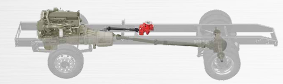
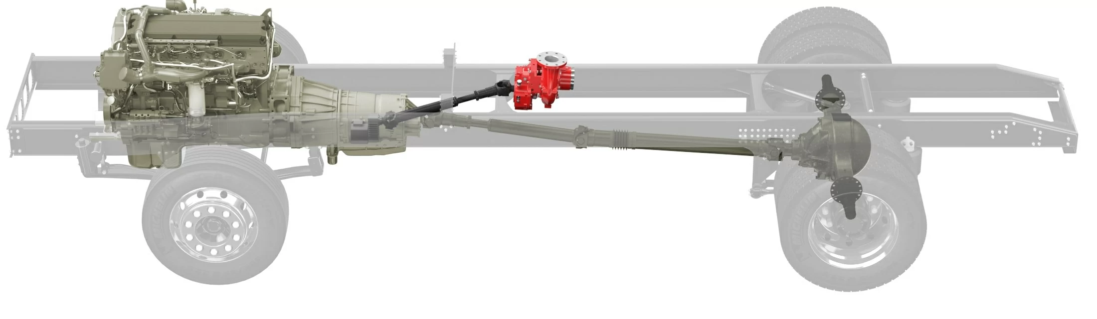
PTO (Power Take Off):
In a power take off application, the pump is powered from a power take off , from the vehicle’s transmission. (Shown below) PTO powered pumps have the capability to do stationary pumping but is not restricted to being stationary and may have the capability for pump and roll if desired. If pump and roll is desired, careful attention to detail will be required to ensure the pump is capable of meeting the NFPA stationary rating requirements and meet the objective of the pump and roll requirements set forth by the committee. A typical pump and roll objective is 2 miles per hour at 20 gpm and 80 – 100 psi, but speed and flow needs vary from application to application. It should be noted that PTO driven pump applications gallon and pressure ratings are dependent upon the available torque capabilities of the PTOs of which will be integrated in each application. 10 Bolt PTO’s: A good typical rule of thumb to go by is an Allison 3000 EVS with Left & right PTO openings is capable of powering a 1250 gpm pump and an Allison 3000 EVS with Top and Left PTO openings is capable of powering up to a 1500 gpm PTO driven pump in certain applications. (**OEM review and approval is required) 4000 Allison EVS can PTO power a pump up to 1500 gpm. 6 Bolt PTO’s : Any medium duty chassis that has 6 bolt PTO’s can PTO power a 250, 300 and in some circumstances 500 gpm (**OEM review and approval is required)
Hydraulic:
Hydraulically driven pumps require a hydraulic set up to power the pump which include a hydraulic pump, hydraulic motor and all the other components of a hydraulic package. Hydraulicly driven pump packages accommodate mobile and stationary pump applications and can accommodate pump mounting outside of the “standard” or more commonly used locations.
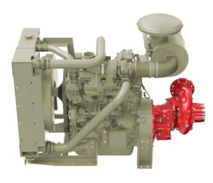
Direct Drive:
Directly driven pump applications accommodate stationary and mobile pumping and are typically packaged with the pump / engine combination being mounted on a flat bed or trailer type application. The fire pump is directly coupled to an engine using a bellhousing assembly and drive plate integration. Directly driven pumps come in a vast array of sizes and flow capabilities from small portable packages all the way to big industrial applications with pumps of 4,000 gpm or more.
ARFF, Motor Pumps, CAFS and Foam Systems
To learn more about other offerings from Waterous including ARFF, Motor Pumps Compressed Air Foam Systems and Foam Systems, visit WWW.WATEROUSCO.COM.
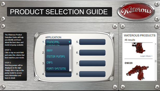
Product Selection Guide
You can also find a product by using the Waterous Product Selection Guide. This mini-configurator can narrow your choices down to a specific model that will then link to the specific product page on the Waterous web site. Click on the following link for an easy step by step guide for selecting your next Waterous product:
HTTP://PRODUCTGUIDE.WATEROUSCO.COM/
Conclusion:
While this guide will help you narrow down your choices in your apparatus, Waterous is available to answer your specific pump application questions. Reach out to Waterous at HTTPS://WWW.WATEROUSCO.COM/CONTACT/.